Headbanger Headphone Amp
The Headbanger Headphone Amp
I've messed with this circuit
quite a bit, it's very capable despite it's small size. The original
site where I got my information for it is here
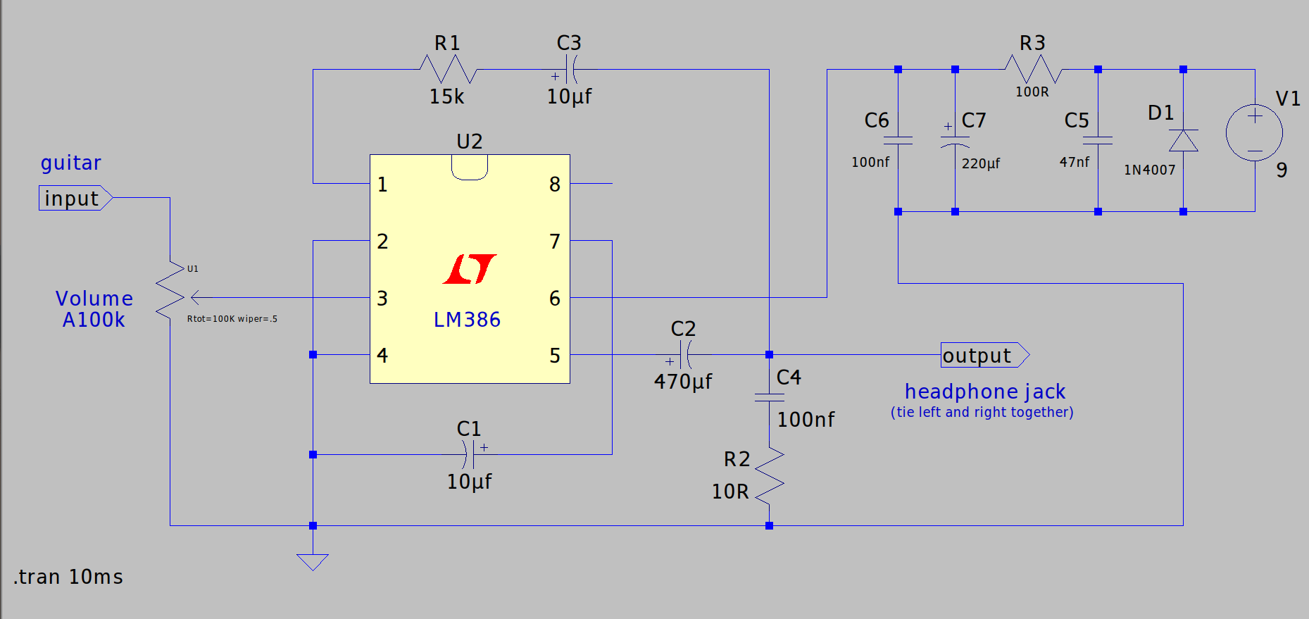
The schematic I worked from:
I just made it so it would work with a +9 volt supply.
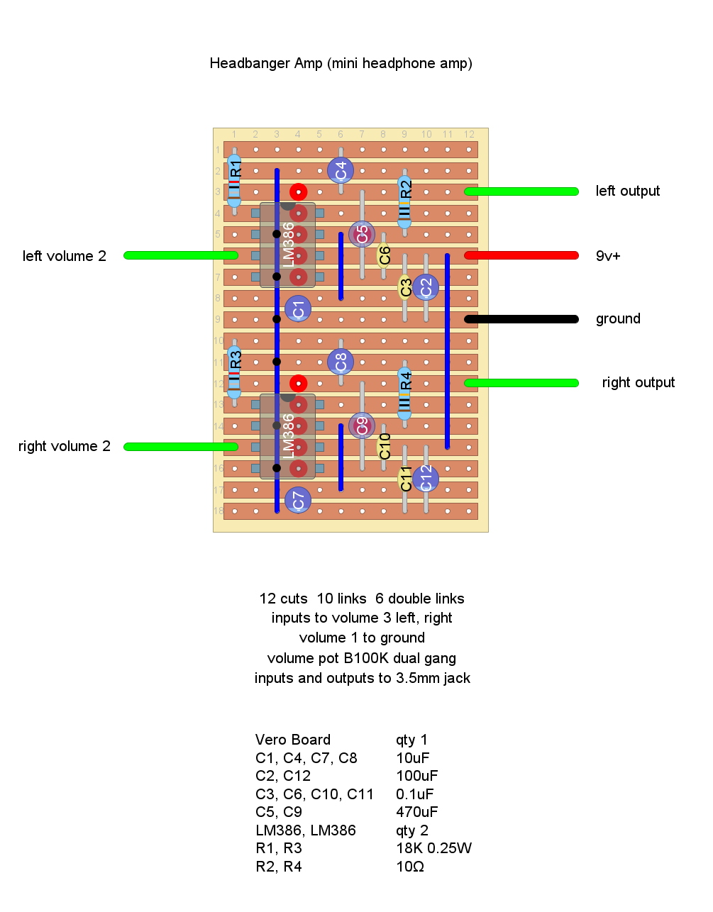
A vero layout I created for the same, the power and ground wires could be
relocated below the output lines to keep them away from signal but I don't think it's necessary.
As stated below R2 and R4 should be at least a 1/2 watt resistor with an air gap between them and the board for longevity.
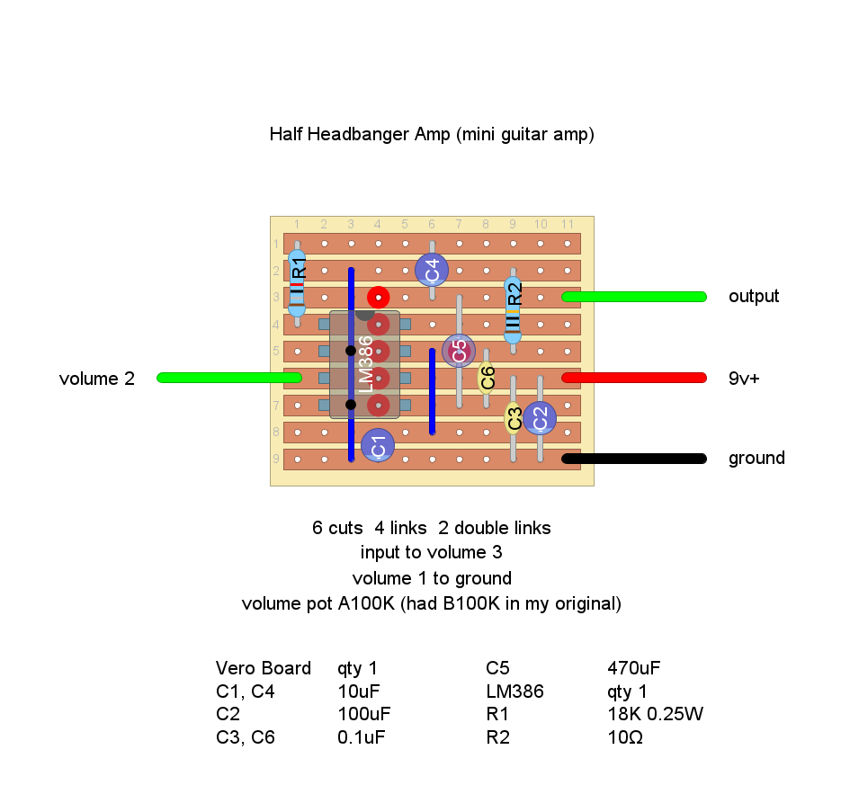
Here is a schematic I did for a guitar to headphone amp.
Also here is a vero layout for half of the Headbanger which works well for a preamp, boost or just a mini practice amp.
Update 1/12/26:
Was messing with this today getting some measurements and discovered that the 10 ohm resistor R2 gets quite warm if running at high volumes for short times.
I used 1/4 watt so I would recommend that resistor to be at least a 1/2 watt and probably good idea to have an air gap between that and the board.
You could add a tone control if you wanted to, I haven't done that with this circuit. Usually whatever I'm running through it has it's own tone control.